Part 3: Optical sensor board
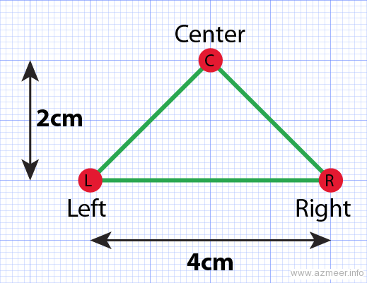
After visiting many similar projects and testing loads of designs we settled down to use 3 sensors arranged as a triangle. Our assumptions of deciding the distances were based on:
- The board is white (formica)
- The standard 2cm black color electrical tape is used for the lines
Testing the prototype
Arduino Uno has 6 analog inputs, each at 10 bit resolution (giving 0 to 1023).
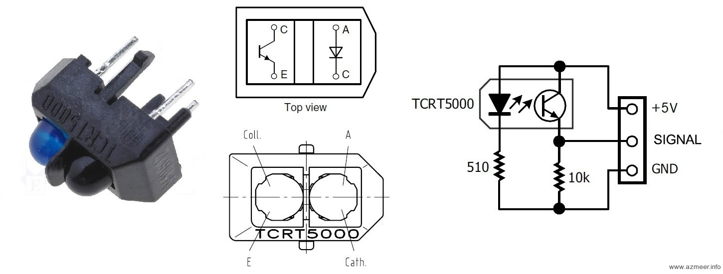
We used TCRT5000 reflective optical sensor to detect the black line. Here are the connections.
We used the following circuit to test our case with 3 scenarios. R2 was replaced with TCRT5000 optical sensor circuitry.
- Open to air
- Reflecting black (black electrical tape)
- Reflecting white (white paper)
Here’s the code we used to test our optical sensor. It simply reads the value on analog port 0 and send it back to the PC via the serial port. We used the excellent open source RealTerm serial port monitor to log the output. You could also use the built-in serial port monitor of the Arduino IDE (but this cannot save the output).
The 2 second delay is required for us to see the feedback of reflective object change. We used 9600 baud, 8 bit data without parity (default setting).
/*
read analog data from A0 and send to PC via Serial port
*/

void setup() {
  // initialize the serial communication:
  Serial.begin(9600);
}

void loop() {
  // send the value of analog input 0:
  Serial.println(analogRead(A0));

  // wait a bit for the analog-to-digital converter
  // to stabilize after the last reading (min 2 milli sec):
  delay(2000); //2000=2 sec
}
We received following results:
- Open to air – less than 50
- Reflecting black (black electrical tape) – less than 300
- Reflecting white (white paper) – more than 900
We were happy with the prototype and went ahead with building the final sensor board on Vero board.
Reading 3 analog sensors
The trick when using multiple analog sensors is to read them twice, with a small delay after each read (5ms is good), then discard the first reading. This is because the ADC multiplexer needs switching time and the voltage needs time to stabilize after switching.
Basically the first analogRead call causes the multiplexer to switch, the delay gives the voltage time to stabilize, then your second read should be much more accurate with less jitter.
/*
read analog data from A0-A2 and send to PC via Serial port
*/

int sensor_L, sensor_C, sensor_R; //optical sensor values
String tmp;
int ADC_stabilize = 5;

void setup() {
  // initialize the serial communication:
  Serial.begin(9600);
}

void loop() {
  //take a snapshot
  sensor_L = analogRead(A0);
  delay(ADC_stabilize); //stabilize
  sensor_L = analogRead(A0);
  delay(ADC_stabilize);

  sensor_C = analogRead(A1);
  delay(ADC_stabilize);
  sensor_C = analogRead(A1);
  delay(ADC_stabilize);

  sensor_R = analogRead(A2);
  delay(ADC_stabilize);
  sensor_R = analogRead(A2);
  delay(ADC_stabilize);

  tmp = "L=" + String(sensor_L) + " C=" + String(sensor_C) + " R=" + String(sensor_R);

  // send the value of analog inputs:
  Serial.println(tmp);

  // wait a bit for next reading
  delay(1000); //1000=1 sec
}
More info here: http://arduino.cc/en/Tutorial/AnalogInputPins
We needed to detect the following patterns in order to traverse the path successfully.
- Sharp left turn
- Sharp right turn
- Left bend
- Right bend
- T junction
- Cross (or round-a-bout)
References:
- Excellent guide to Vero Board prototyping
- A free tool for Vero Board circuit design
- Another serial monitor from Microsoft


Hi,
Can you tell me why you prefered optical sensors rather than using IR analog sensors.
Hello.
I think that you have reversed the polarity of the LED in the schematics schema of the TCRT5000
I checked other web sites and they had reverse polarity compared to yours and I was not able to make it work when I connected according to your schematic.
Schematic is directly taken from Vishay. The URL is provided above.