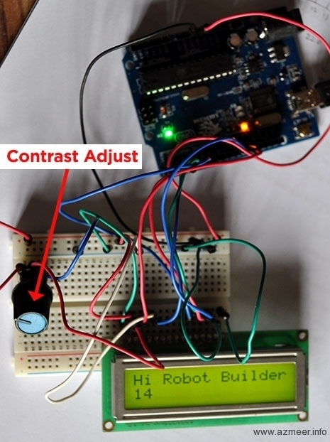
We wanted a LCD to display various settings and generally to impress the crowd 🙂 We ended up using the standard 16×2 LCD display.
Here’s the test code we used.
/*
 Demonstrates the use a 16x2 LCD display.

  The circuit:
 * LCD RS pin to digital pin 12
 * LCD Enable pin to digital pin 11
 * LCD D4 pin to digital pin 5
 * LCD D5 pin to digital pin 4
 * LCD D6 pin to digital pin 3
 * LCD D7 pin to digital pin 2
 * LCD R/W pin to ground
 * 10K resistor:
 * ends to +5V and ground
 * wiper to LCD VO pin (pin 3)

 This example code is in the public domain.
 http://www.arduino.cc/en/Tutorial/LiquidCrystal
 */

// include the library code:
#include <LiquidCrystal.h>

// initialize the library with the numbers of the interface pins
LiquidCrystal lcd(12, 11, 5, 4, 3, 2);

void setup() {
  // set up the LCD's number of columns and rows:
  lcd.begin(16, 2);
  // Print a message to the LCD.
  lcd.print("Hi Robot Builder!");
}

void loop() {
  // set the cursor to column 0, line 1
  // (note: line 1 is the second row, since counting begins with 0):
  lcd.setCursor(0, 1);
  // print the number of seconds since reset:
  lcd.print(millis()/1000);
}
A great video on Arduino LCD control:


Hello
could you share your full code please? or at least could you share how did you detect the patterns in order to traverse the path successfully?
I’m also making a line follower and I have a problem in detecting the patterns.
Hello Azmeer,
how did you guys combine your codes? I don’t see the final code anywhere.
Could you post it somewhere?
Thanks!